Overview
The heating system is designed to be fully automatic to keep the indoor temperature constant, currently set at 22 degrees, for any outdoor temperature below that and down to 0 degrees. That really means that usually there’s nothing to do other than to casually give it a thought and observe that it’s working fine.
For convenient adjustment, the system includes a comfort control in the lounge room for varying the temperature about 4 degrees below or 2 degrees above the controller’s target temperature. Primarily, the target temperature is set on the control unit which in practice only controls the temperature of the radiators, keeping them appropriately warmer or cooler so as to maintain the constant indoor temperature as the outdoor temperature changes.
|
Note
|
The working principle is to regulate the forward flow temperature to the radiators in relation to the outdoor temperature in such a way that the indoor temperature remains constant. |
The theory is that the heat loss of a house is linear with respect to the temperature difference between indoors and outdoors, and empirically this has been measured to be roughly 300 W/C (Watt per degree Celcius) for this house. Thus, if it goes down to 0 degrees outside, the energy needed to keep the house at 22 degrees is roughly 6.6 kW (= 300 W/C * 22 C).
When the outside is warmer than 22 degrees the heating system runs on idle with the water circulating through a closed 3-way valve and the heater merely maintaining a hot tank.
The circulation pump ages more gracefully if left running while using only 70 Watt of electricity.
The heater also ages more gracefully if left running, but it’s more costly to run and one may consider turning it off during the summer season. Though it might then "make some fuss" when turned on again in the autumn.
Further, if the house is warmed up through a spell of hot days, one should wait with turning on the heating during subsequent cooler nights as this might otherwise prolong too high indoor temperature while the indoor air and timberwork etc. cools down.
Schematic Diagram
The heating system consists of two piping circuits, heater and radiation, delineated by a "shunt" or "bypass" path in between, at the point of the 3-way valve
The automatic 3-way valve can be considered the primary control point, and is continuously variable between being fully-closed (where the heater is completely bypassed and the flow is recirculated in the radiation side), and fully-open (where no water flows through the bypass and all is directed through the heater). By adjusting between these two conditions it proportions the mix of heated and recirculated water, delivering the amount of heat as needed to the radiators.
The heater circuit has a gas heater that keeps a tank of water at high temperature. This is fed as "hot inlet" to the motor-controlled 3-way valve to be mixed in with the radiation circuit flow.
The radiation circuit has a circulation pump that constantly circulates the water through the radiators. The return flow is split up as "cold inlet" to the 3-way valve and "cold return" to the heater to match the "hot inlet" flow consumption.
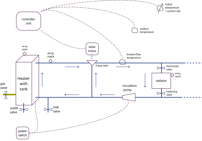
Figure 1. Heating System Schematic Diagram.
There are three thermocouples for sensing the temperatures of the forward flow water, of the outdoor temperature as well as of the indoor temperature. The control unit combines these into the continuous control of the 3-way valve setting; opening it when too cold and closing it when too warm.
Pictures of things
These are pictures of the particular things talked about in this description of the heating system. Each of them is further discussed in some detail in the following sub sections.
The Controller Unit
The controller unit is mounted inside the left-hand cupboard above the sink in the laundry. This provides the continuous control of the 3-way valve according to its programming.
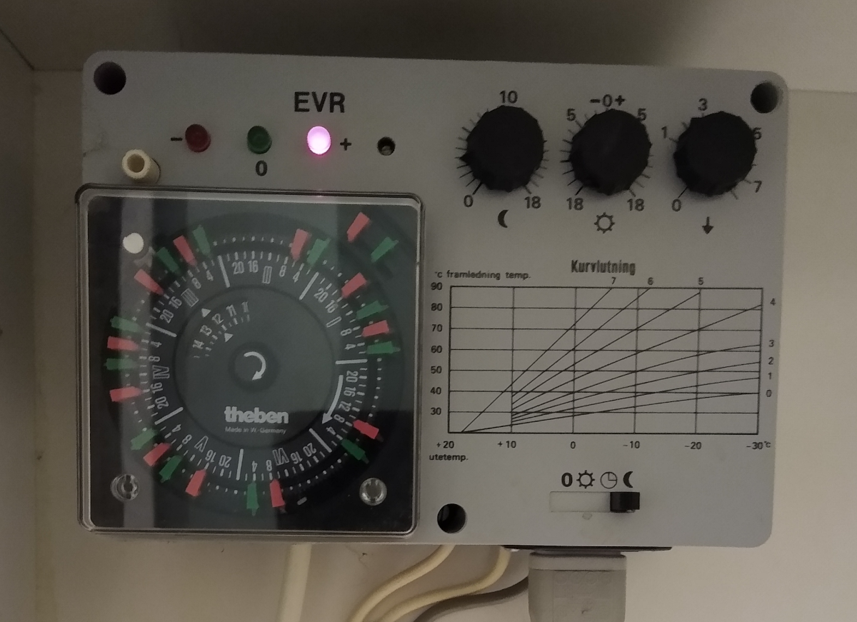
The unit has 3 sections for its programming and a display of its current control status.
-
Down-left is a per-hour weekly programming wheel for alternating regularly between "day time" and "night time" temperature levels. The timer may need to be adjusted to current day and time (with the centre knob), and then alternating red and green markers are placed for when transitions between day and night time temperature levels should occur.
NoteThe fall and rise of temperatures is rather sluggish (and typically "fall" is faster than "rise") and in reality there seems to be no energy gain with preserved comfort by using this programming. -
Top-right are 3 programming dials, from left to right:
-
The left dial sets the reduction in forward flow temperature for the night time level relative to the day time level control curve as set with the next two dials. The dial is set at a 2-3 times higher number than the desired night time temperature reduction.
-
The middle dial sets the up/down control curve offset that applies equally across all outdoor temperature levels. This corresponds to the desired forward flow temperature when it is 20 degrees outside, and the dial is set at roughly 2-3 times the difference from that relative desired indoor temperature. I.e. for the 22 degrees indoor temperature target, the dial should be set to about 5.
-
The right dial sets the control curve slope angle as per the diagram below the dials, which shows the slopes for forward flow temperatures relative outdoor temperatures. Note that the diagram has "colder outdoors" towards the right.
-
-
Bottom-right is a run mode selector for "off", "day", "timer" and "night" operation. The "off" mode means to keep the 3-way valve closed; the "day" mode means to control the valve for the day time temperature target: the "timer" mode means to control the valve as programmed on the timer; and the "night" mode means to control the valve towards the night time temperature target.
-
Top-left is a panel with 3 LED lights to indicate the current control signal for the 3-way mixing valve. The left light marked with "-" indicates that the valve is closing; the right light marked "+" indicates that the valve is opening; and the middle light marked "0" indicates that the valve is held as is.
There’s also a small "screw" to the right of the right LED for adjusting the control pulse interval to act faster or slower.
The indoor thermocouple with comfort dial
The indoor thermocouple with comfort dial is mounted on the North lounge room wall.
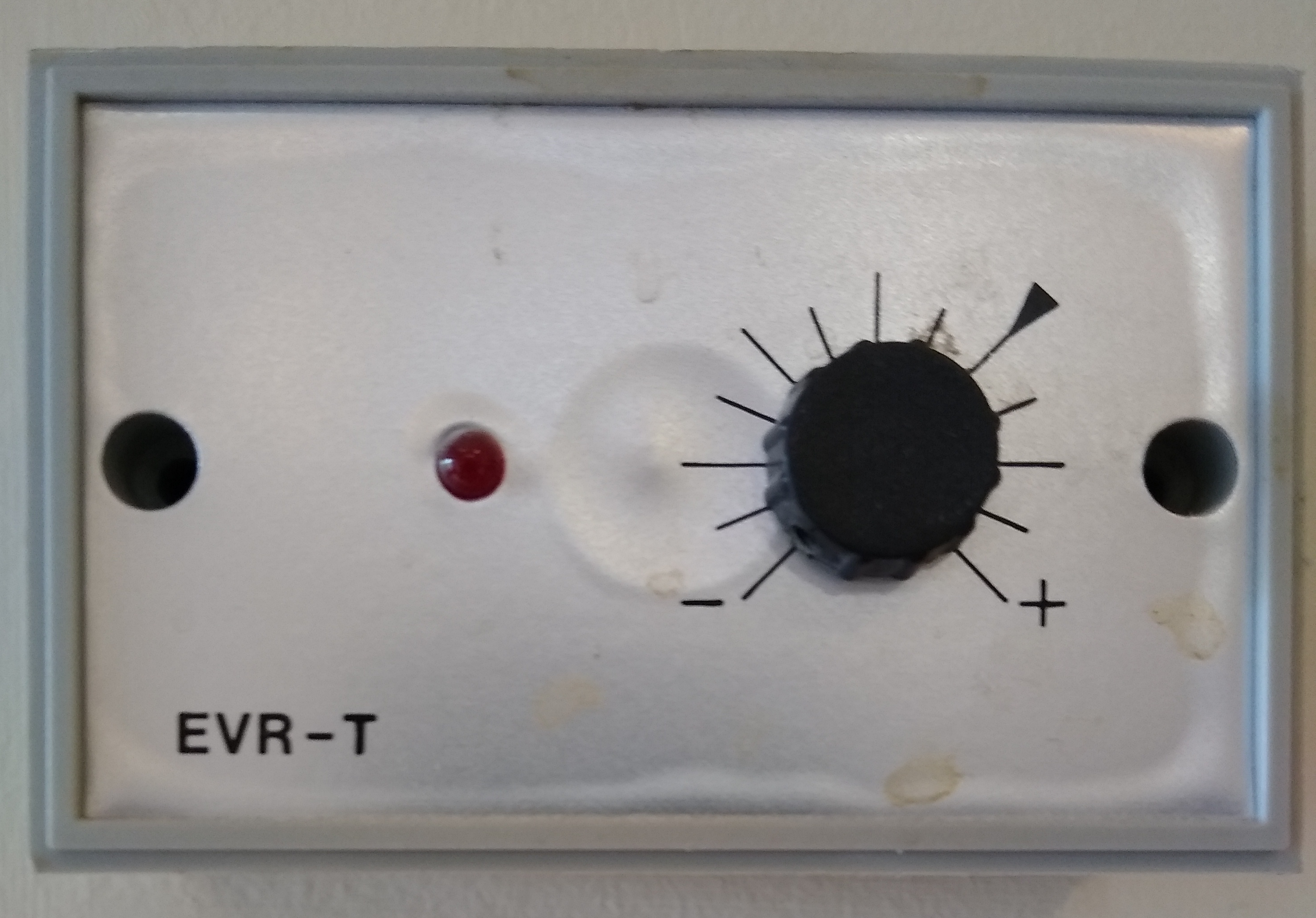
It has a red LED light that is on when the indoor temperature is below current target, and off when it is above.
The target can be varied with the control dial to "a little bit" lower or higher temperature; the full swing is roughly -4C to +2C relative to the programming of the control unit. In principle this setting just adds to the controller unit’s middle control dial (the level of the curve).
The motor controlled 3-way valve
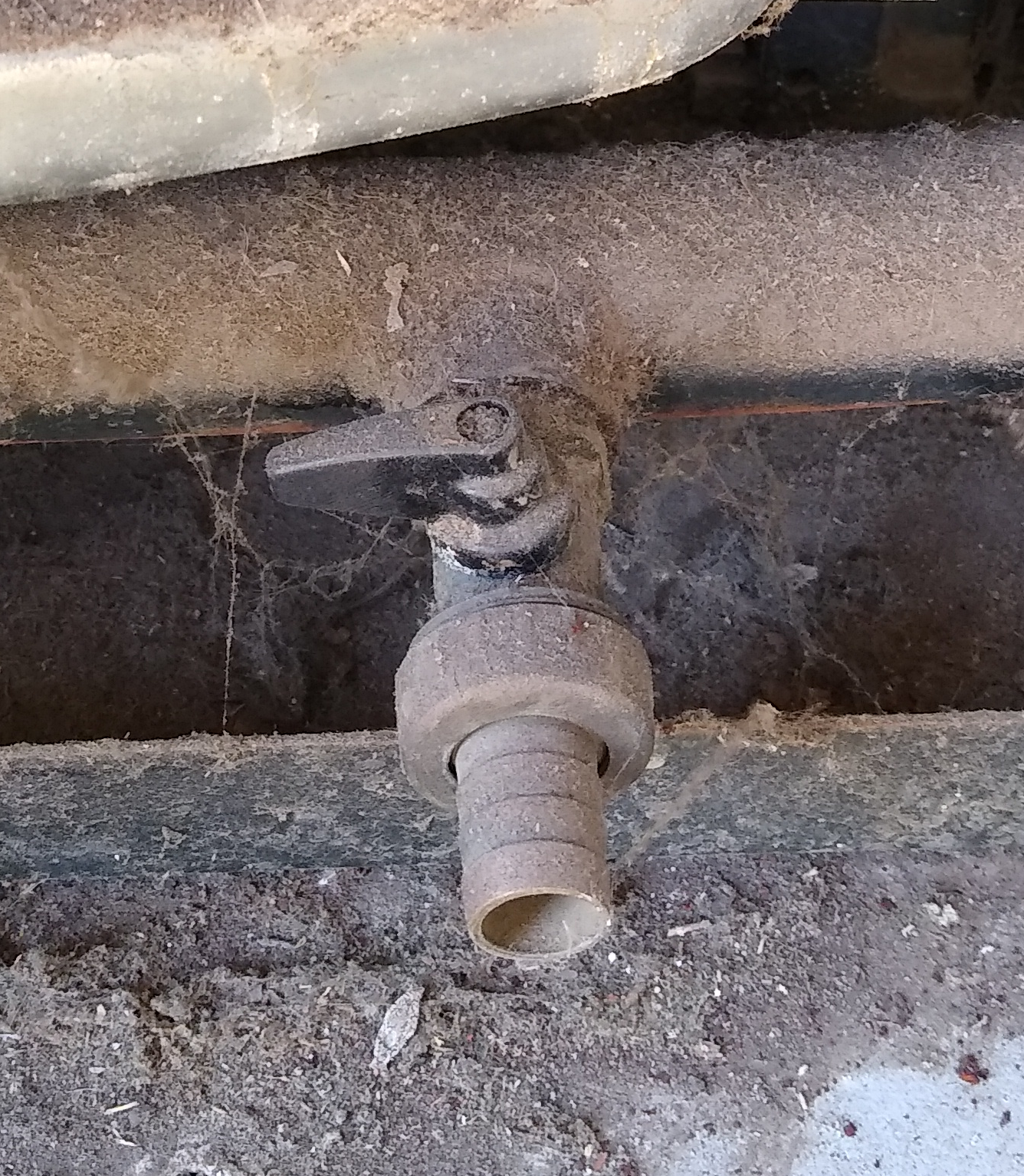
The motor controlled 3-way valve is found outside by the West wall, to the left of the heater, and usually covered by a plexi-glass hood.
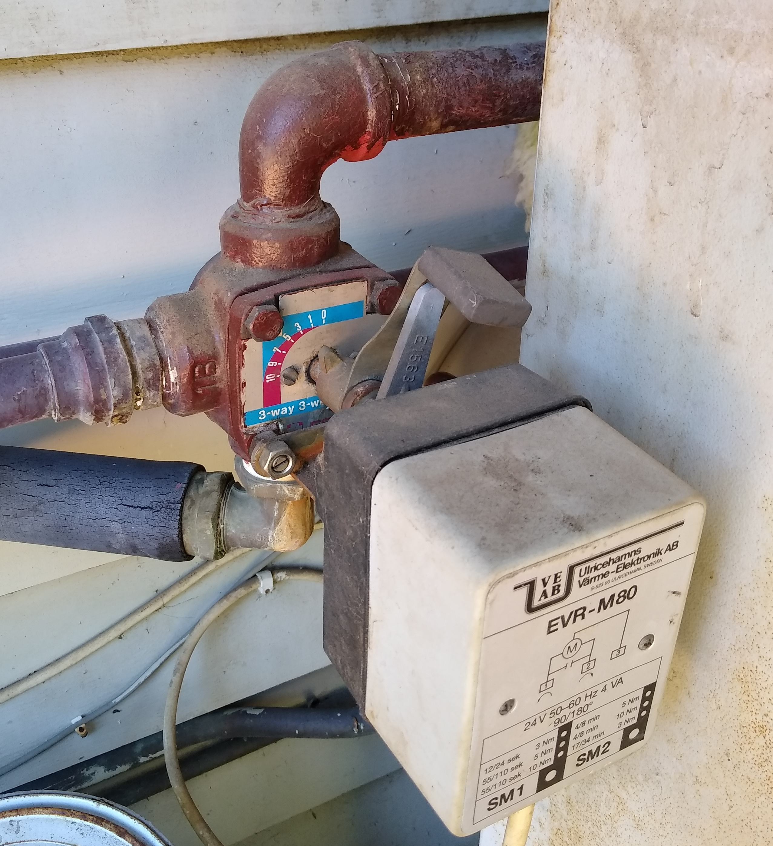
The control handle leans right when closed and left when opened. The 3-way valve has the hot inlet at the top, the cool return inlet at the left, and its mixed outlet at the bottom.
|
Note
|
The control axis has an o-ring seal that wears out every 10 years or so. When that happens there will be a dripping leak originating from the control axis seating. There are replacement parts in the cardboard box under the controller unit. |
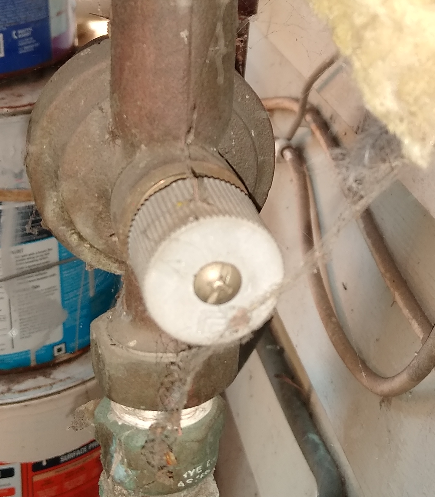
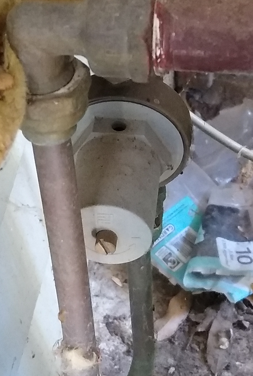
The circulation pump
The circulation pump is mounted on the radiator return flow to the left of the 3-way valve.
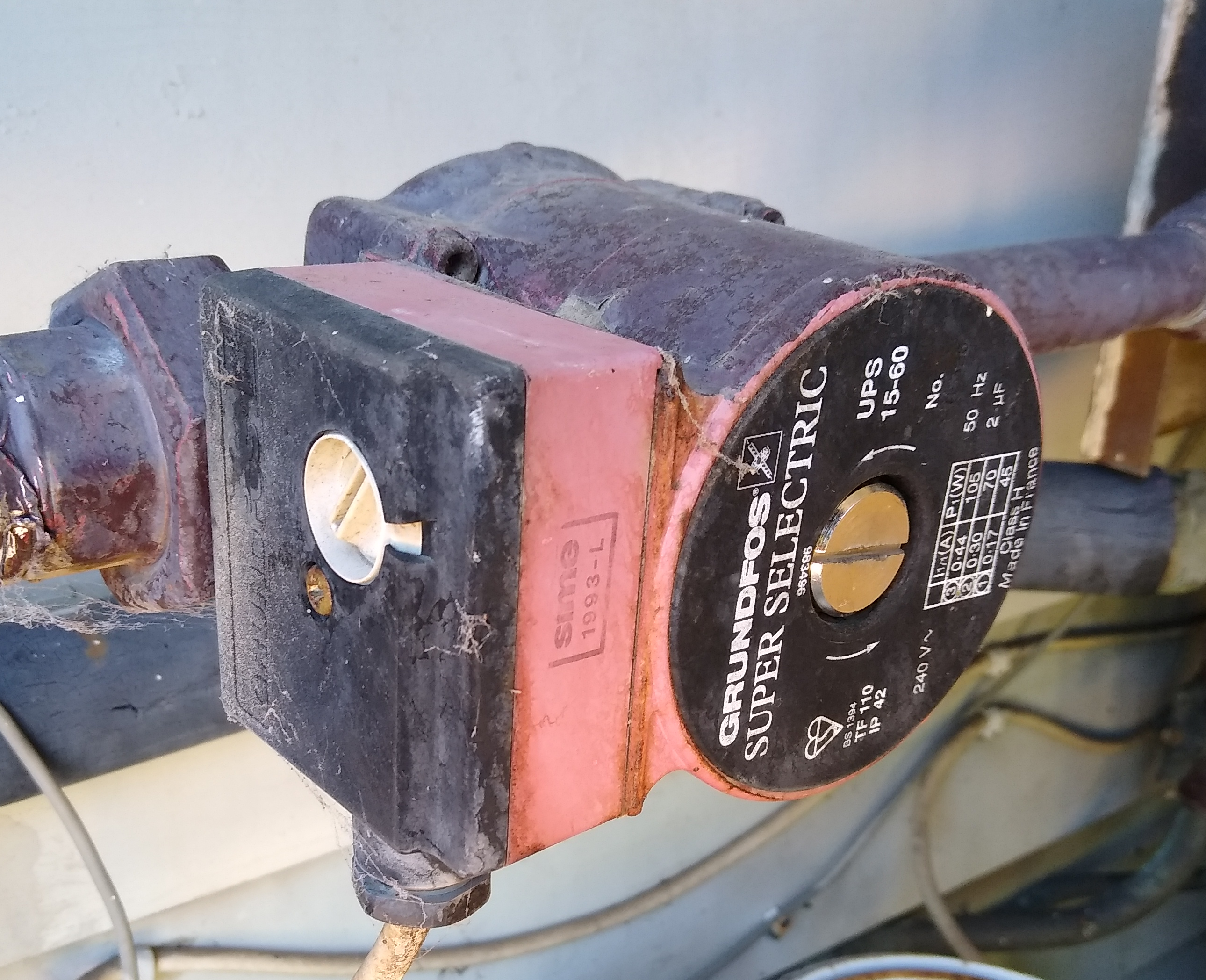
The pump has an airing screw covering the rotation axis (the West oriented face) and a speed setting dial on the left side. The settings are "low", "medium" and "high", and the current setup is designed for and tuned to the middle (medium) setting.
For maximum service life, the circulation pump is best left on at all times since the circulating water lubricates it and keeps corrosion at bay. If needs be, the pump may be turned off by the heater switch (together with the heater control system). The pump power cable is fixed inside the switch while the heater is via a power plug.
The outdoor thermocouple
The outdoor thermocouple is in a box that is mounted on the West wall above the shed roof and shaded by the rain water down-pipe.
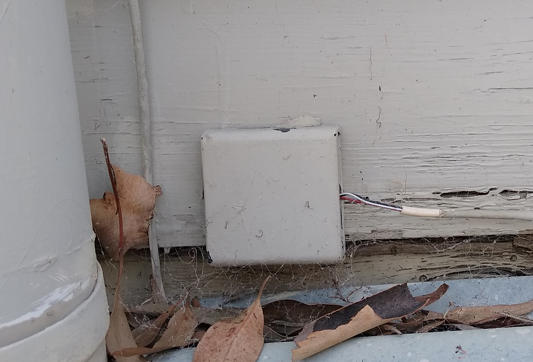
It’s important to keep it clear of leaves so it can capture a true air temperature.
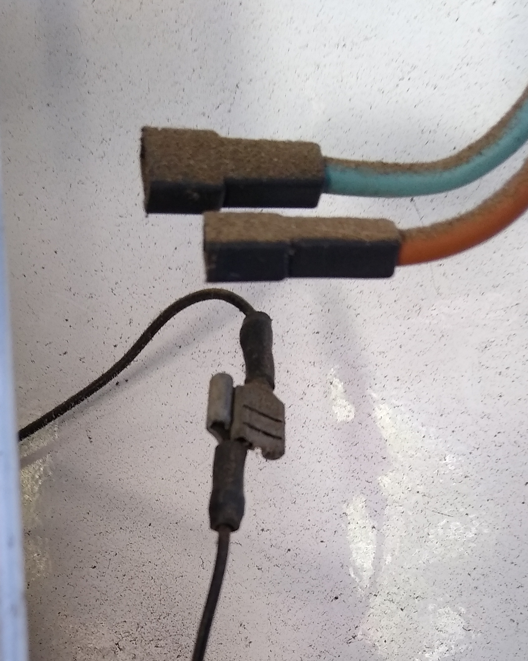
The forward flow thermocouple
The forward flow thermocouple is hidden in the pipe insulation.
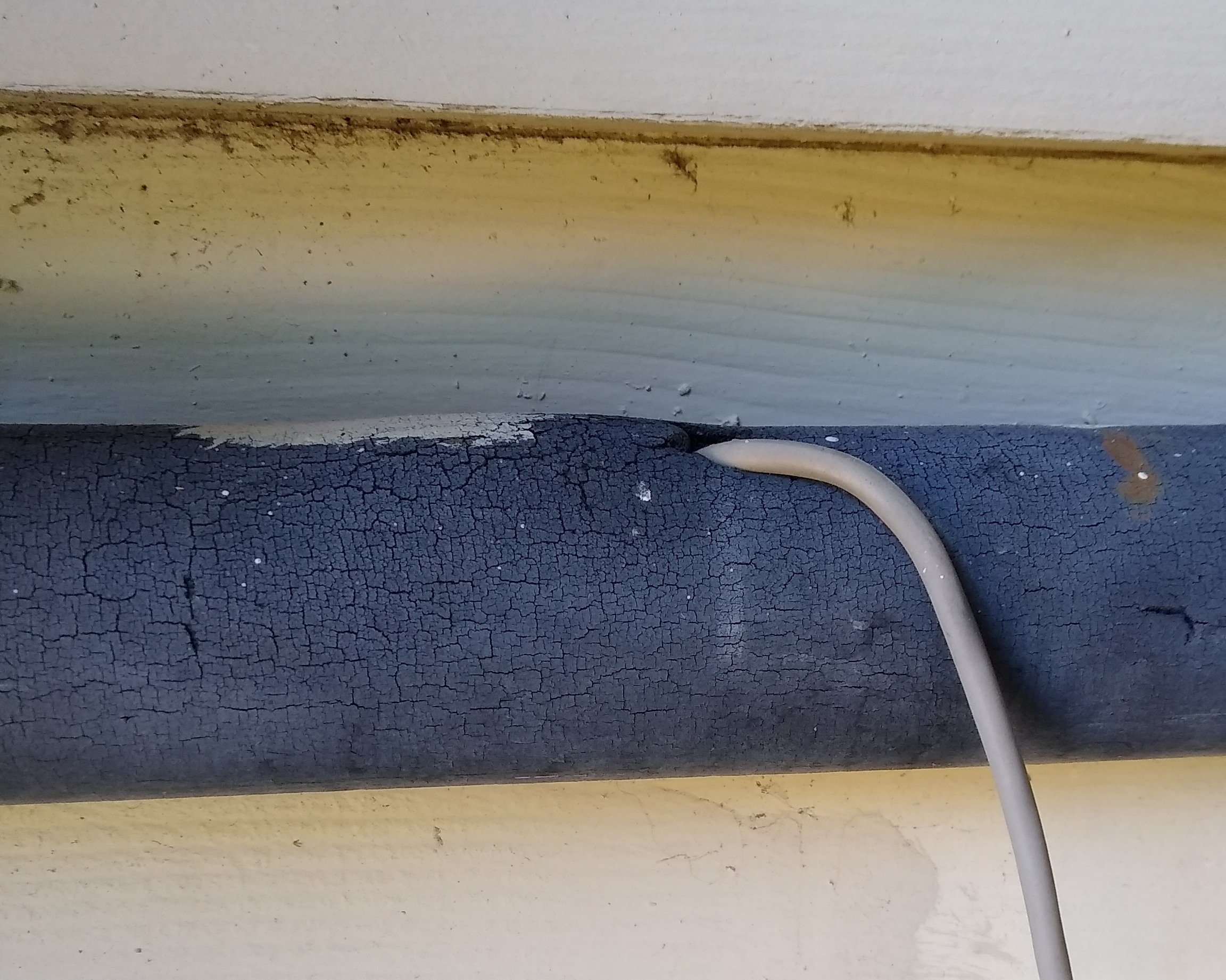
There is no maintenance needed for this apart from making sure that the lead, which hangs loose from the controller unit cable outlet, is undisturbed.
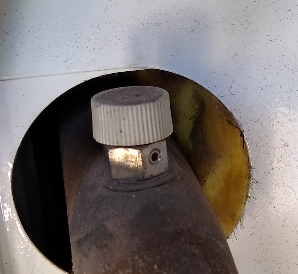
The hot water airing nipple
The hot water airing nipple sits to the right at the back of the heater.
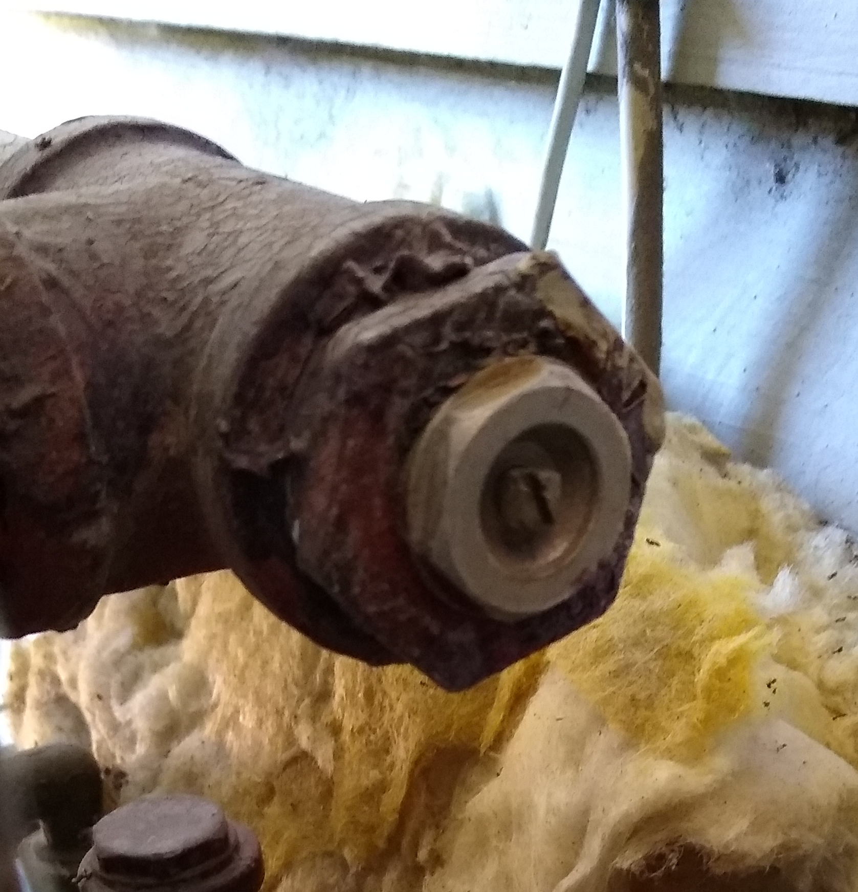
This is only used when the system is refilled with water, to ensure that there is no trapped air in that part of the piping.
Radiator airing nipple
Each radiator has an airing nipple at its left or right top end, typically straight above its control valve.
These are used (opened) when the system is refilled, to release any trapped air accumulated in the radiator. A radiator with trapped air is cooler at the top than in the middle, and it may also have a "bubbly" sound.
Heater airing nipple
The heater airing nipple is found behind the heater door on the protruding water pipe to the right.
This is only used when the system is refilled with water, to ensure that there is no air trapped in the heater tank.
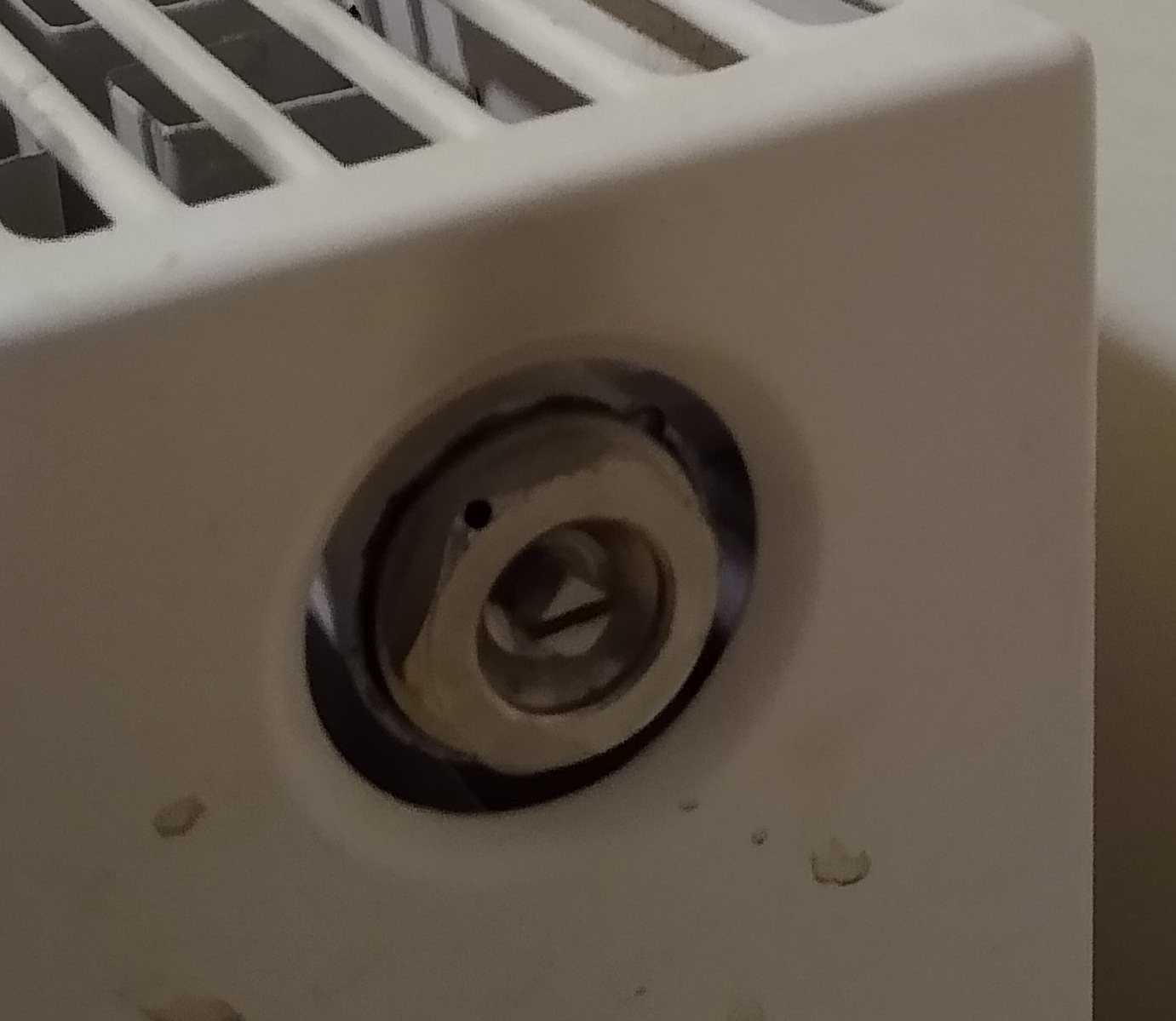
Radiator balancing valve
Each radiator has a balancing valve which is a screw covered by a screw-on lid.
The balancing valves are used so as to achive a flow balance among all the radiators, and avoid that the heated water flows too fast through some radiators while not at all through other. Balancing is a slow procedure that involves adjusting one of those that seem too open or too closed by half a turn, then wait an hour or so to check again that all radiators feel just right: a functioning just right radiator should feel cool at the bottom and warm at the top, transitioning rougly in the middle.
-
If the transition too high, then the water flows too slowly through it and it calls for further opening its balancing valve.
-
If the transition too low, then the water flows too quickly through it and it calls for further closing its balancing valve.
|
Note
|
Balancing should be done with all control valves fully opened. |
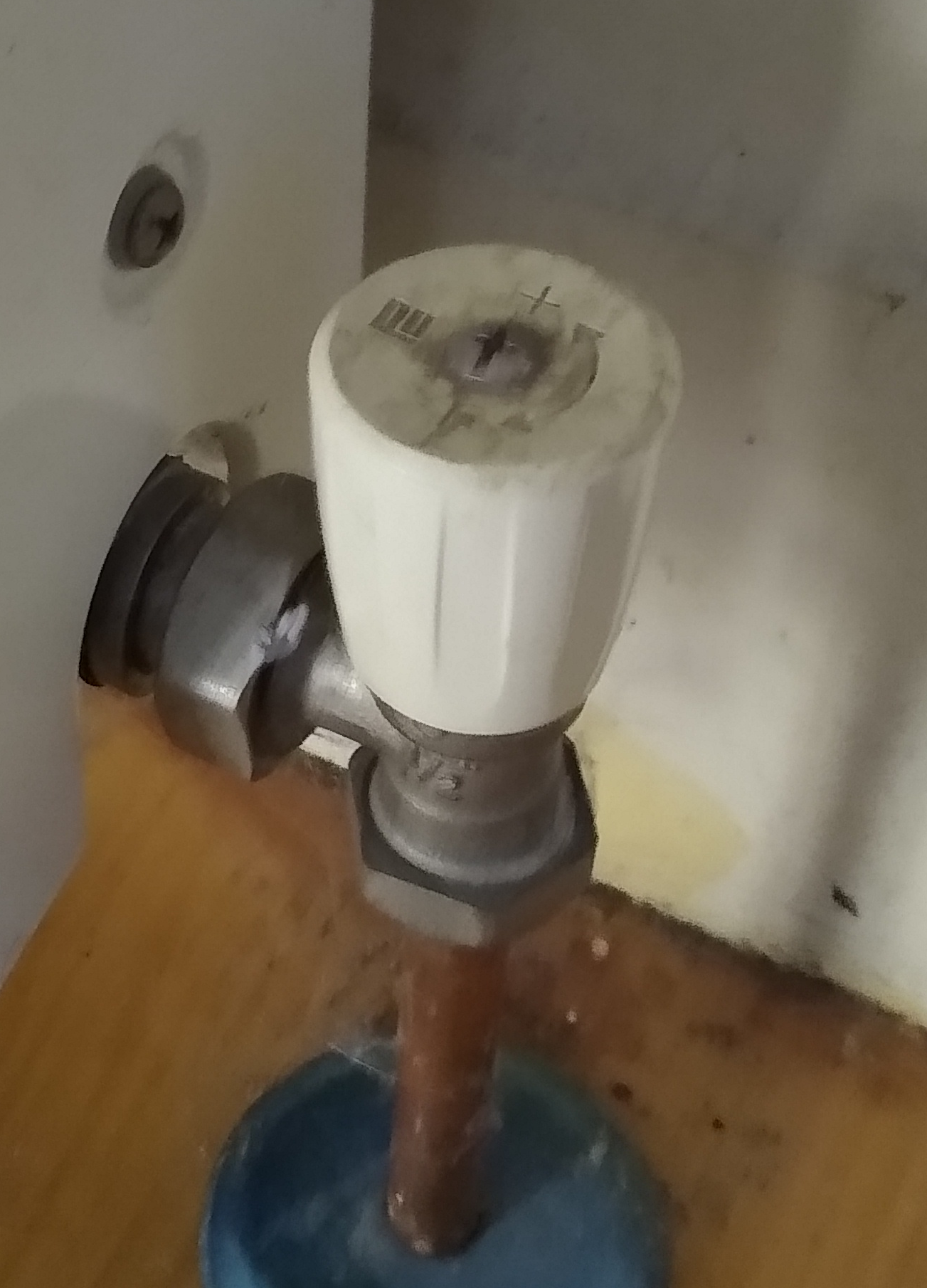
Radiator thermostat valve
Each radiator has a control valve opposite to the balancing valve, and these are either thermostat valves or manual valves.
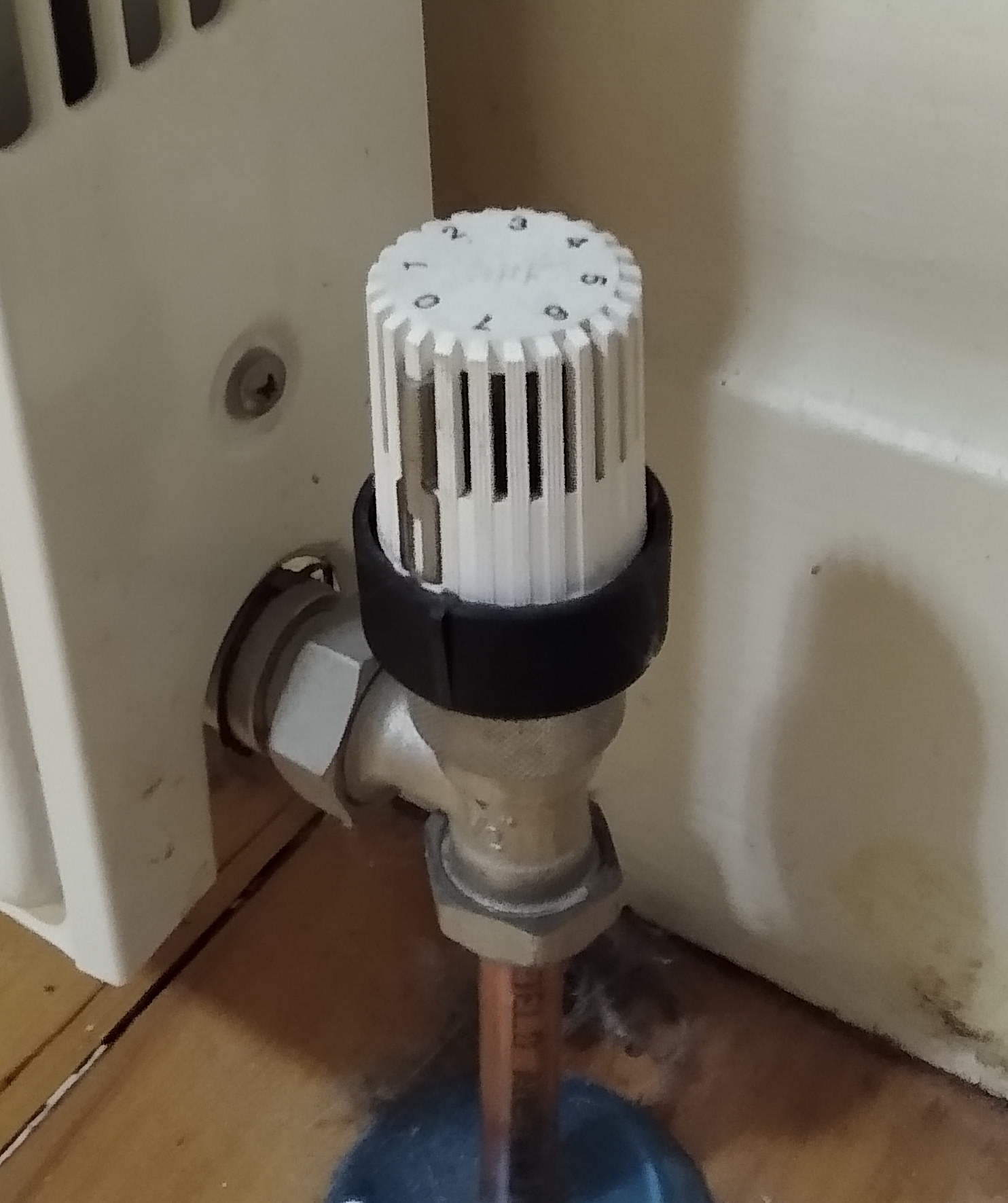
A thermostat valve opens and closes the valve automatically depending on whether the local temperature for the valve is below or above its setting, determined by the position to which it is turned. The lowest setting is about 12 degrees, and the highest setting is 22 degrees (or more accurately, as "physically programmed" into the valve knob by releasing the the metal lock pin, then twisting the dial as appropriate, and then push back the lock pin)
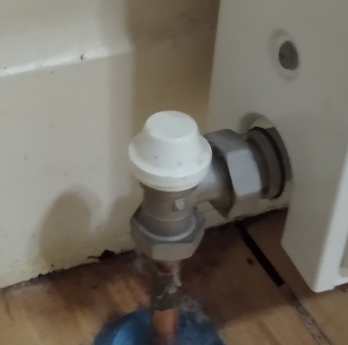
Manual radiator valve
Each radiator has a control valve opposite to the balancing valve, and these are either manual valves or thermostat valves.
A manual valve is opened or closed manually and it stays as set.
Heater gas valve
The gas valve is found to the left at the back of the heater.
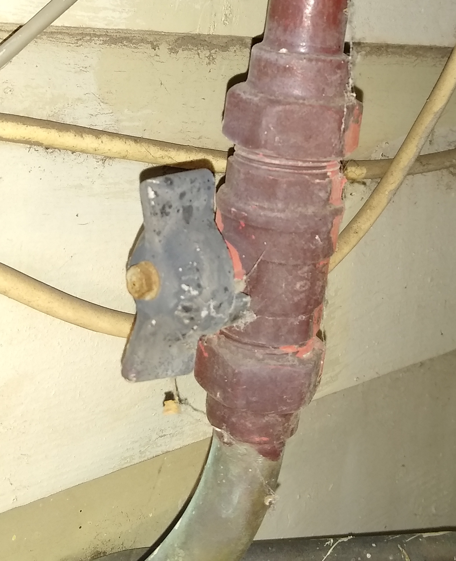
It is open when the "wings" are vertical and closed when the wings are horizontal.
Gas control knob
The gas control knob is inside of the heater door, and to the left, on the gas control house in the middle behind the heater door.
This is pressed and turned slightly to allow the flow of gas, firstly a limited flow for lighting the pilot flame and secondly the main gas flow for the heating. It must be held pressed down while operating the ignition button for starting the pilot flame, and then be slowly released until it stays without pressure, enabling the main gas to flow and be ignited by the pilot flame.
The knob remains down while the heater is operating, although the heater will turn off and on the main flame as needed according to its own thermocople. The heater operation is programmed with the heater temperature dial.
Heater ignition button
The heater ignition button is inside of the heater door, mounted on the gas pipe below the gas control house in the middle behind the heater door.

This is a piezo-electric igniter for the heater’s pilot flame, and it is pushed, maybe repeatedly, while holding down the gas control knob for igniting the pilot flame.
Pilot-flame inspection hole lid
The pilot flame inspection hole lid is found inside of the heater door, further down just above the burner unit and slightly behind the main gas flow pipe.
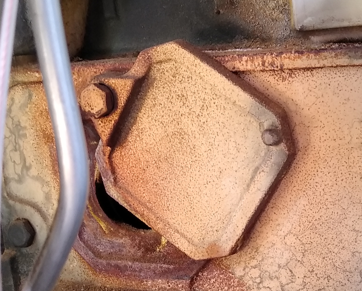
The lid gets hot and should be closed when the heater operates. When opened one can look down into the burning chamber to see the pilot flame nipple and the flame itself, if any. Obviously useful when turning on the flame, but the lid should be closed otherwise.
Pressure sense bypass
The presure sense bypass is seen inside the heater door, in the middle and slightly below the gas control housing.
The bypass is done by the ad-hoc connection of the two cables instead of connecting them to the low-pressure sensor, which aged and became faulty. Instead one must keep a light eye on the system to avoid the heater running without tank water, since if it were to run without tank water the temperature sensor may fail to detect enough heat to turn off the burner before there is other damage to the unit.
"Monitoring" the system usually means to just notice that the house is cosy as per normal, and it only requires action when that’s not the case. Then: check that there is water pressure above 0.5 [kg/cm2] that the pilot flame is burning, then that the 3-way valve operates and that the circulation pump works. (Refer to "Temperature and pressure gauge" below)
For me it has been only to find that the pilot-flame has gone out, which may happen due to a very strong wind, or twice in late summer when I reduced the tank heat level too much (which seemingly for some reason led to the pilot-flame exhausting as it got cooler outside).
Heater switch
The heater switch is mounted on the West wall to the right of the heater.
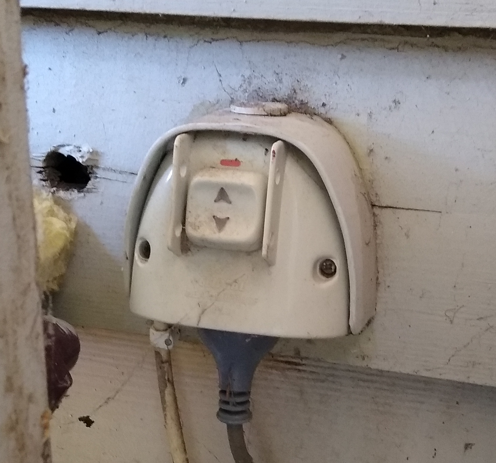
This turns off the electricity to the heater via the plugged in cord. It powers control logic including the relay valve for the main gas flow but it doesn’t control the pilot flame.
The circulation pump also gets its power from the heater switch via the separate cable from inside the switch.
Temperature and pressure gauge
The combined temperature and pressure gauge is found inside the heater door, high up to the left.
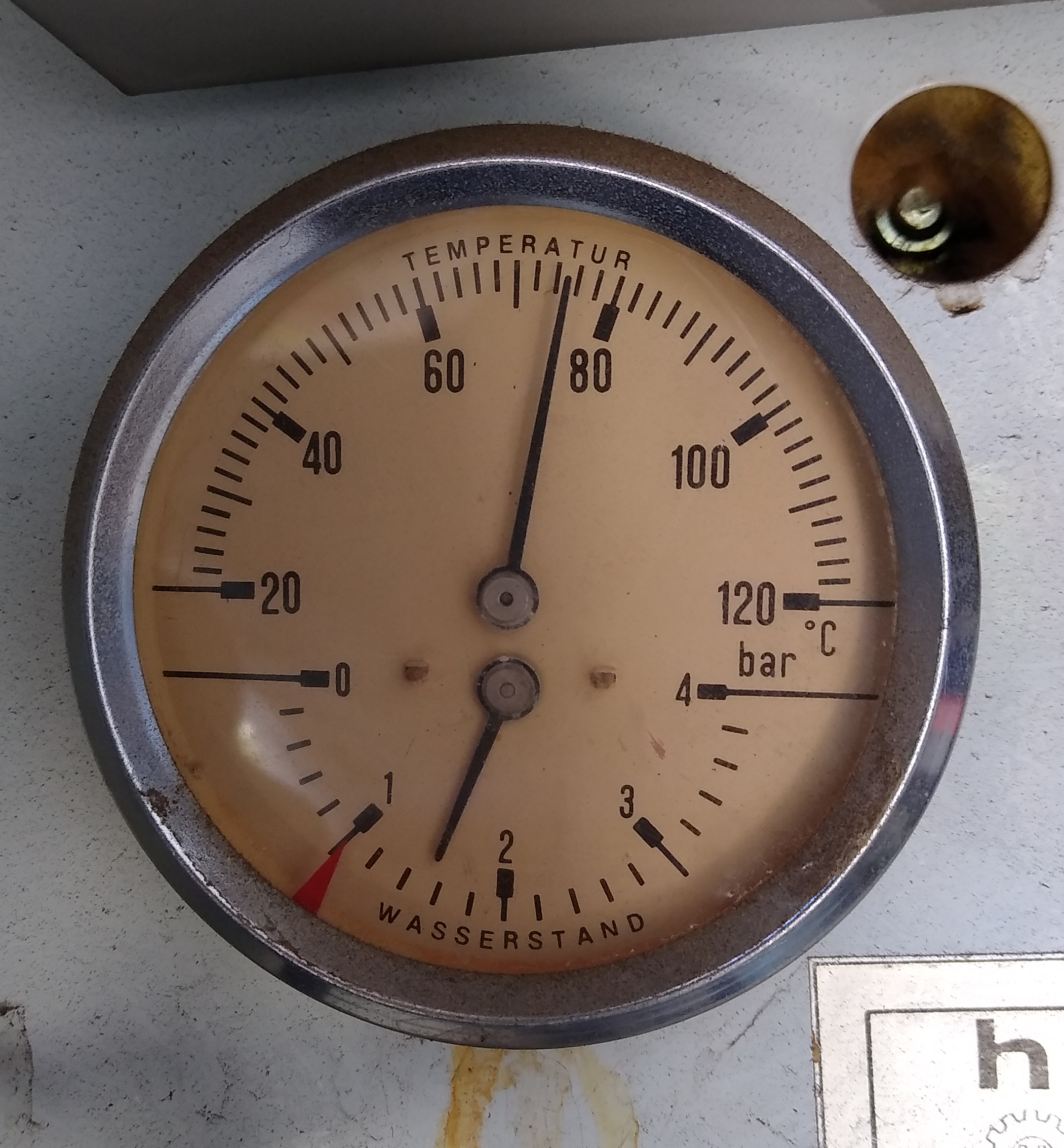
The larger dial shows the temperature of the heater tank water, which typically varies between about 50 degrees and about 80 degrees. The smaller dial shows the water pressure in the tank, in bar, where "1" indicates a 10 m water pillar.
When the system is filled, the tank pressure should show at least 0.5 since that’s the height difference between the water tank and the top of the upstairs radiators. When heated the pressure may rise above 1, depending on how much air there is in the system.
Heater temperature control dial
The heater temperature control dial is found inside the heater door, high up to the right.
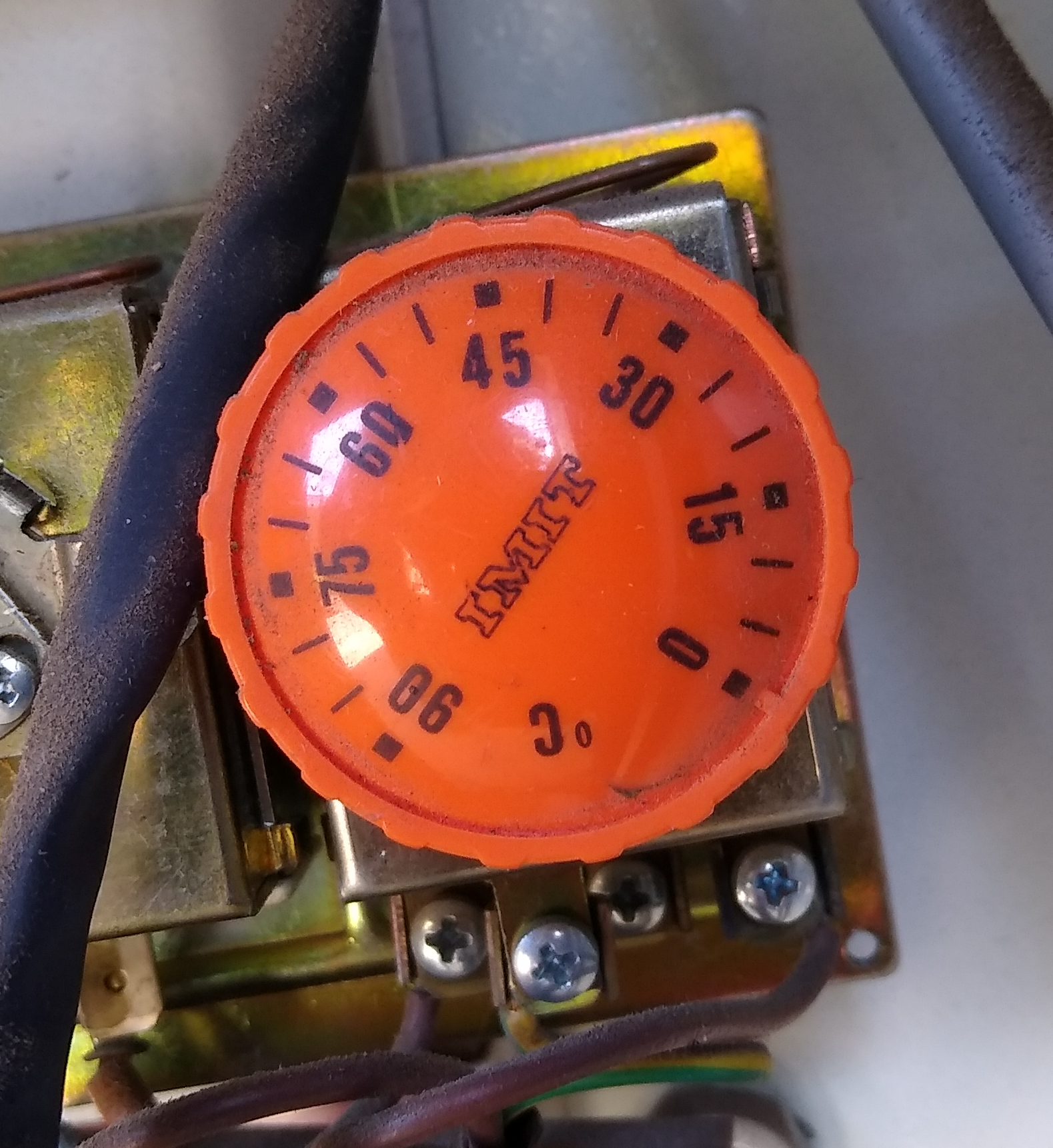
Although it has numbers there is no strong correlation between those numbers and actual tank water temperature. It does however serve to control roughly where the temperature interval is, although there is generally no need to change that at all.
Outlet valve
The outlet valve is found inside the heater door, at the very bottom.
This valve is opened for emptying the water from the system. Make sure the heater is off, eg by turning off the gas valve, before emptying. The system holds about 100 litres of water.
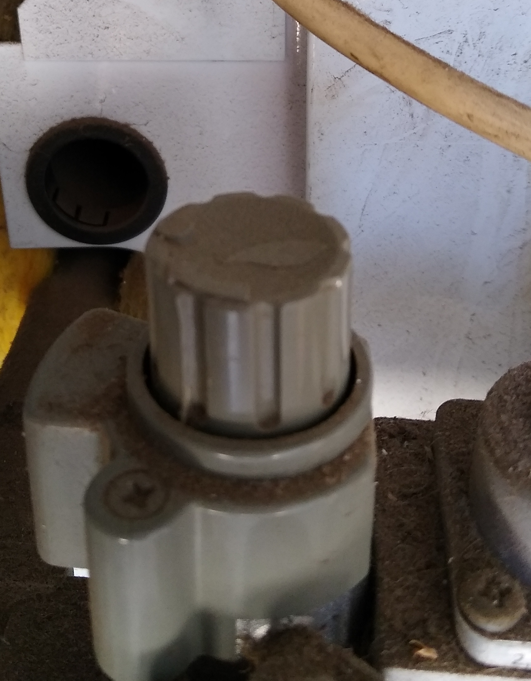
Water inlet valve
The water inlet valve is found straight behind the heater, accessible from the right.
This is actually a pressure-difference valve with a manual open/close setting. When closed it doesn’t let water through and when opened it lets water through until its outlet side reaches the programmed pressure. It is programmed by adjusting the pressure spring at the opposite side from the valve grip.
Water inlet valve pressure spring
The water inlet valve pressure spring is found straight behind the heater, accessible from the left.
The spring is loosened or tightened with a screwdriver. It should be adjusted such that the valve closes when the heater tank pressure is 0.6.
Notes on Operations
How to turn off the system
In normal operation, "turning off" means only to switch the controller unit mode to "off" and leave all else running as per normal. Setting the control unit to "off" mode causes it to close the 3-way valve, which stops any hot water from being consumed. Otherwise:
-
Turning off the gas by the gas valve will ensure the heater does not make heat.
-
Turning off the heater switch also stops the heater from making heat although it keeps the pilot flame going. Turning off the heater switch stops the circulation pump.
-
Radiators with thermostat valves can be turned to a minimal setting which keeps the valve closed down to (from memory) a local temperature below 12 °C.
-
Radiators with manual comfort valves can be fully closed.
How to turn on the system
-
Ensure there is water in the system. The outlet valve should be closed, and the water inlet valve open with the water inlet valve spring adjusted so that the pressure gague inside the heater stay put at about 0.6 [bar] while all the radiators are emptied of air by briefly opening their airing nipples.
Likewise, the hot water link pipe and the heater tank should also be
emptied of air.
-
Ensure the circulation pump is running at medium setting and is duly aired. The latter is done by opening the big screw in the center of its rotation axis slightly to make sure there is some water dripping out and then tighten the screw again.
-
Ensure the gas valve is open by confirming its handle wings point vertically.
-
Ensure the heater’s pilot flame is turned on. This is done by holding down the gas control knob while pressing the ignition button a couple of times with short pauses in between. Keep the control knob down several seconds after the pilot flame is turned on, then release it slowly. The knob should follow slowly a bit while turning, and then stay down as the main gas flow is released and ignited by the pilot flame. There’s typically a noticeable "whoff" sound when the main gas flow ignites.
-
Finally ensure that the control unit operation state is set appropriately, and then check that the motor control movements correspond to the LED light signals.
How to verify normal operation
"Normal operation" can only be verified when the outdoor temperature is a few degrees below the desired indoor temperature. Basicaly the daily maintenance observation is merely to confirm that it’s a cosy 22 degrees (thereabouts) inside regardless of outside temperature.
In more detail, the radiators should be radiating heat and ideally be warm at the top and cool at the bottom. By sliding a hand from bottom and up, the warmth should be first felt close to the vertical middle of the radiator.
The radiator’s balancing valve may be used to adjust it; opening it will lower the cold-warm line and closing it will raise the cold-warm line of that radiator. Note however that such a change actually affects the flow through all radiators, and that system balancing needs to be done slowly, incrediby slowly, by changing one valve at a time by only half a turn with an hour or so in between successive valve changes.
Replacing the heater
Some final words: we had started looking into replacing the heater, which runs on gas, with a heat pump, which runs on electricity. This would be quite doable since the maximal forward flow temperature needed is in achievable range, but in pactice the estimated maximal power needs of 6.5 kW however makes it somewhat complicated.
To this end let me refer you to Jake Williams at "Nissl Eichert Hydronic Heating" (www.nissleichertheating.com.au) who came, looked and discussed this thoroughly with us. One take out from that was the principal design of installing a 500 l water tank and a pair of 4 kW heat pumps. In that system only one heat pump at a time would be in use most of the year while both would kick in during the few coolest weeks where more power is needed.
A total of 8 kW might still seem tight to cover an estimated need of 6.5 kW. But it appeared to be complicated the obtain domestic heat pumps larger then 4 kW and using an industrial scale heat pump would bring additional concerns about placement and noise reduction.
Enjoy.